XGCD Optical Design, Jan 22, 2024
Meeting Notes
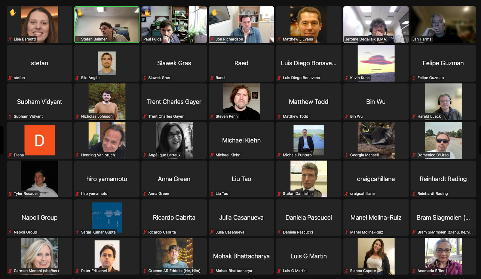
85 participants + 7 (napoli group) = 92!!! (see screenshots at the bottom)
Intro slides (Lisa, Jan)
Common challenges in CE and ET, useful to discuss each other choices
Why not just scale up the LIGO optical design?
CE slides (Jon Richardson, Paul Fulda, Craig Cahillane for CE team)
Jon Richardson
There are a number of reasons why the LIGO optical design is inadequate.
One issue is optics size in the corner station and clipping loss. 40km CE has about 12cm beam radius. Needs about 70cm diameter ITMs. 500ppm SEC loss requirement. About 10kW PRC power.
LIGO TCS: CP+RH at ITM. Correct quadratic term in curvature with RH, but there are higher-order terms to be corrected. CP is meant to do it.
CP needs to be eliminated in the higher-power condition of future detectors like CE/ET. Plan is to demonstrate a new technology in LIGO A#.
Scattering into HOM by BS depends on angle of incidence (AOI). Can be as high as 100ppm. Low AOI is favored for TC of BS since it decreases divergence of MECH-x / SEC paths.
Paul Fulda (CE slides continued)
Starting with 450 arm-cavity finesse. High arm finesse would enhance SEC loss, degrade squeezing due to increased mode mismatch, and it poses additional challenges to short SEC scenarios.
CE HF response is impacted by second SEC resonance due to long arms, and this issue influences the optimal choice of SEC length. Short SEC is preferred from a detector response perspective, but makes it hard to accumulate Gouy phase and expand to a 12cm beam.
Several corner layouts are conceivable. Many of them were invented to reduce the AOI on the BS, no final decision yet, work in progress to downselect.
Jerome Degallaix for Einstein Telescope Optical Design Team
Arm cavity basic design already – reminder of parameters on page 3
Focus of current work is on recycling cavity design
Difference between ET-HF and ET-LF, this talk focuses on ET-HF
Status of design for recycling cavity – requirements on slide 9 and 10
Important requirement: BS not larger than aVirgo+
Page 12: design for ET-HF
Page 13: current ET-HF layout, 45 aoi on BS
Page 17 – work plan
Matt Evans: Is the power density on ZM2 a problem?
- Jerome: ZM2 reflective mirror, and not such a big beam
Matt Evans: Did your team confirm that having the BS in the telescope (i.e., highly curved wavefront) is ok? This is something we also worry about
Lisa Barsotti: not much on impact of 10 dB squeezing requirement in your talk. Is it because the impact of HOM resonance in the band is more important for CE, and not such a big deal for ET?
- True, a lot of the HOM won't be in the ET band, but mode-mismatch still very relevant for ET, I would assume (Kevin)
- Jerome: important for ET to follow up on that
Jon Richardson: can you please clarify: in your case, your arm cavity design is basically done, correct?
- Yes, but we will go back to the arm cavities fine tuning geometry once the recycling cavity design is done
- Jon: it might be useful to look at where the HOM fall, and optimize that to make them out of band
Stefan Ballmer: What imposes the size limit on the BS? 2.3 cm – is thermo-refractive noise or something else?
Jerome: No, this noise is much smaller, this is motivated by thermal lensing inside the BS
Stefan Ballmer: do you have a good sense of tolerances and specification for a lens in Compensation Plates?
- Example in Virgo for PRM and SRM
- Not yet, but we need to have a way to adjust for deviations from optimal, but will look at robustness vs cold/hot defects so as to make tolerances not stringent
Paul Fulda: astigmatism in the recycling cavity – we worry a lot about this for CE for some of the designs. Are you considering more complex optics to compensate?
- Challenging to align, beside manufacturing problems – so preference to maintain spherical mirrors, but we will investigate more. Same work on going for Virgo, so we will develop tools and process
Jon Richardson: SEC loss —- 1000 ppm nominal design for ET, less stringent than 500 SEC for CE, although also 20kW in PRC which is higher than CE. Are you also worried about the AOI on the BS?
- Not considered lower AOI on BS yet for ET, but still possible and we will look into it
- Alessio Rocchi: Advanced modeling still to be done for thermal compensation, it will be done once basic optical design done with beam size on BS
Matt Evans: AOI on BS – can you change your mind later on, or is it an infrastructure issue that you have to decide ASAP?
- For recycling cavity not so urgent, infrastructure will be able to accommodate different options
- Stefan Hild: Advantage of Xylophone, flexibility in space due to simple suspensions, even if underground detector, still room for making changes
Jan Harms: Infrastructure considerations important for CE too, even if not underground, given how some of the corner layout options look like. How does the CE infrastructure look like for the corner? The corner station will be elevated somehow with respect to the ground? Is all going to be on one plane?
- Matt: Some idea of how it would look like, but good point, we haven’t yet done a real infrastructure layout; probably an array of chamber, we are not yet there. Virgo has some experience with that, everything could be on the second floor.
Stefan: We also haven’t thought about how our input optics connect to the recycling cavities and filter cavity. Still working on that – have you thought about that?
- Jerome: we have designed another tunnel for the filter cavity, so from the infrastructure point of view yes, but we need to optimize the layout.
Lisa Barsotti: do people have concerns about low AOI on the Beam Splitter? Do people think it is a risky thing, and need some validation, or straightforward?
- Jan: you need to be very sure about the beam line (for example in configuration 17), otherwise risky –maybe for CE ok, but for ET seems risky.
- Matt: I would imagine a sequence of chambers next to each other, and you need to have a hall with enough space, but for an above ground facility it doesn't seem too complicated. But having ITM before or after the crossing it is a big deal, in mind more so than the zig-zag before the ITMs
- Paul: some constraint on SEC length
- Paul: focus now on optical layout, and then look later at integration with vacuum layout. So optical configuration priority now, maybe we will carry forward 2 or 3, and then down select including infrastructure considerations
- Jamie: I strongly encourage both projects to think about not baking in single optical design that's hard to change. An important lesson from the first gen is that you will probably want to change it in the future.
Stefan Hild – One topic if time permits: What is people’s take on tools. Is Zeemax the ultimate solution? Or would people be interested to have an OptoCAD successor / IfoCAD / or similar?
- Paul: CE working with gTRACE (from KAGRA) → Solidwarks → ZEMAX
- Jon: we like gTRACE interface, only 2D drawings, it can output files compatible with existing methods within the lab (Solidworks and ZEMAX)
- Discussion in ET? OptoCAD not maintained, ZEMAX commercial tool (only used by US teams), what are the best options?
- Anamaria: ZEMAX complicated to use, experts are not many, 10k per license or something like that
- Developing a code also not free
- Daniel Brown: personally I find Zemax quite awkward and complex to use for interferometer layouts. I've been experimenting with a Python CAD constraint library combined with raytracing, so you specify lengths, angles, and it layouts the IFO. It's all early days but happy to work with people on it to see if it goes anywhere – 3D models
- Shall the whole community use one tool, or have more than one is better? It would be easier to have one tool
- Steve Penn: Zemax has been bought by Ansys. One wonders if that would lead to lower priced licenses for academics
Lisa, Jan: Thank you all, good discussion, very useful for both teams, more of these meetings will happen! Stay tuned.
Participant screenshots:


DIGESTED LIST OF ACTION ITEMS
Cosmic Explorer action items: Notes from 4pm discussion (Kevin, Stefan)
- Document and review some of the key, design-driving items:
- ITM lens manufacturing constraints
(metrology a) RoC, b) deviation from ideal / thermal lensing) - Toroidal mirror manufacturing
- BS in convergent beam
- BS angle of incidence constraints
- BS minimum size requirement
- SEC length constraints / Finesse constraints (build on PF aLIGO doc)
- What are angle-of-incidence constraints for all folding mirrors?
- Full 2D layout, including filter and MC cavities
- LB: need to start to produce concept of infrastructure corner layout, even if not for final configuration, to see how the zig-zag and ITM crossing would actually look like
Einstein Telescope action items (Lisa, please edit):
- Cross-checking the calculation about the maximum beam divergence at the BS level
- Checking astigmatism and estimate the associated losses
- 2 or 3 focusing optics in the recycling cavities ?
- Ramp up advanced thermal modeling, as seen for CE that this will be one of the main design drivers
- Review compatibility with 10 dB squeezing
Common interests: